Friday 30 January 2015

FUEL ROD DESIGN

I've found some steel tubing in my dad's shed which I will be able to use for the fuel rod-This has a 16mm diameter and is 2mm thick.
I've decided i'm going to mount this at the end of the intake tube. This is for two reasons; the tube isn't stainless steel and taking Bruce Simpson's advice that this position is much cooler compared to nearer the combustion chamber-with this not being stainless steel this will help avoid it melting; and also as it will be easier to fit in this position-not working with a slanted face.
I'm going to drill 3mm holes along the tube.


I have also got a ball valve and gas tube adapter ready to build the fuel system and a gas cylinder regulator that allows the gas pressure leaving the cylinder to be increased from the standard 300 millibars to 4 bars; this flow will be necessary for proper functioning. I'm going to consult my dad about what fittings will be suitable and available for connecting this all together as his experience holds valuable information.

My worries at this stage is that the fuel rod being the size/thickness it is, it may impede the air flow in the intake sufficiently to prevent the Pulsejet from functioning properly. I'm going to have a look around to see if I can find something more suitable but if not will just try with the current fuel rod. The only way to find out if this has an effect is through testing. With the way I a planning on fitting the fuel rod though, it will be relatively easy to remove and replace with a different one if it causes a problem.

PAPER MOCKUP

I found when trying to print the templates that they were bigger than A3 which is the limit of my printer; I tried finding a way of tiling together A3 sheets to make a larger template but AutoCAD makes this very difficult to do. Instead I took the files to Staples in PDF form for them to print to scale on A1 for like £2 a sheet.
I thought that just to verify my templates and give me an idea of what sort of size the engine will be, I made a paper mock-up of the using the actual templates:


This confirms the templates fit together; I will need to do a test run on the actual sheet metal to ensure they still work including the thickness of the metal; if not I will need to remake some suitable templates and re-test them; this is shown on yellow on the schedule. 

Thursday 29 January 2015

SAFETY

From a safety point of view with me being 17 and this being a school project, I was advised by my supervisor to conduct a risk assessment. It basically outlines my dad supervising me throughout construction etc. and using the necessary PPE like welding masks, gloves ETC.

In terms of whilst actually running the Pulsejet, I'm going to have ear protection to hand as with the jet being an acoustic resonator, it can be very loud. I fire extinguisher will also be close to hand just in case.
Bruce Simpson has said that the engine actually has more chance imploding/crumpling more than exploding so a shield won't be needed. I will keep the area facing the exhaust clear in case any hot metal particles are spat out. I will also keep the control board for the fuel and the gas canister as far away from the engine as possible so once it is started everyone can retreat and control it from a 'safe' distance. If I feel extra precaution is needed I could possibly approach the science department in school and borrow a perspex shield I've seen used to protect students during experiments/demonstrations but I don't feel this will be necessary.

FUEL ROD

From looking at the dates I'm surrounding my schedule on, I have found that I have paid little attention to how I will make the fuel rod; due to the timings of when school closes for half term, if I want to use any of the schools resources (ie. pillar drill) I will need to have it made by the 13th of Feb; I need to decide this imminently.
From a quick look at what other people have done the fuel rod is basically metal pipe with holes drilled in to disperse the fuel-Bruce Simpson tells to use a steel tube with roughly 8mm diameter with 1.5-2mm holes drilled in along it facing the walls of the tube (1.12). He suggests two places to mount it: the end of the intake tube or the cone connecting the intake to the combustion chamber. Colin Furze uses this system; a 15mm diameter tube with 3mm holes punched in along which he mounts at the beginning of the combustion chamber.

SCHEDULE

Having been given a deadline to aim for to complete my artefact by (24th February), I have realised how pushed for time I am and see it fit to create the schedule I mentioned to try and aim for: an ambitious one at that.

Up until now I have had limited progress due to other commitments and a reluctance on my behalf to progress without a proper direction from school in fear of not fulfilling the EPQ requirements.
Looking at what days I can allocate to this project every week I have picked these dates to get certain parts finished by. I am assuming I can complete all the logging of the project and the paperwork in my spare time whilst at school and in the evenings; I won't plan for this time as I hope to just complete it as and when it needs doing.

This is the schedule I'm going to try and follow for February when basically the whole thing will have to be built. 
I am currently restricted to being able to weld on Sundays due to the time involved with setting up the welder/equipment, being supervised, the evenings going dark relatively early and working on Saturdays-this shouldn't be such an issue in the half term.


Sunday 25 January 2015

THEORY

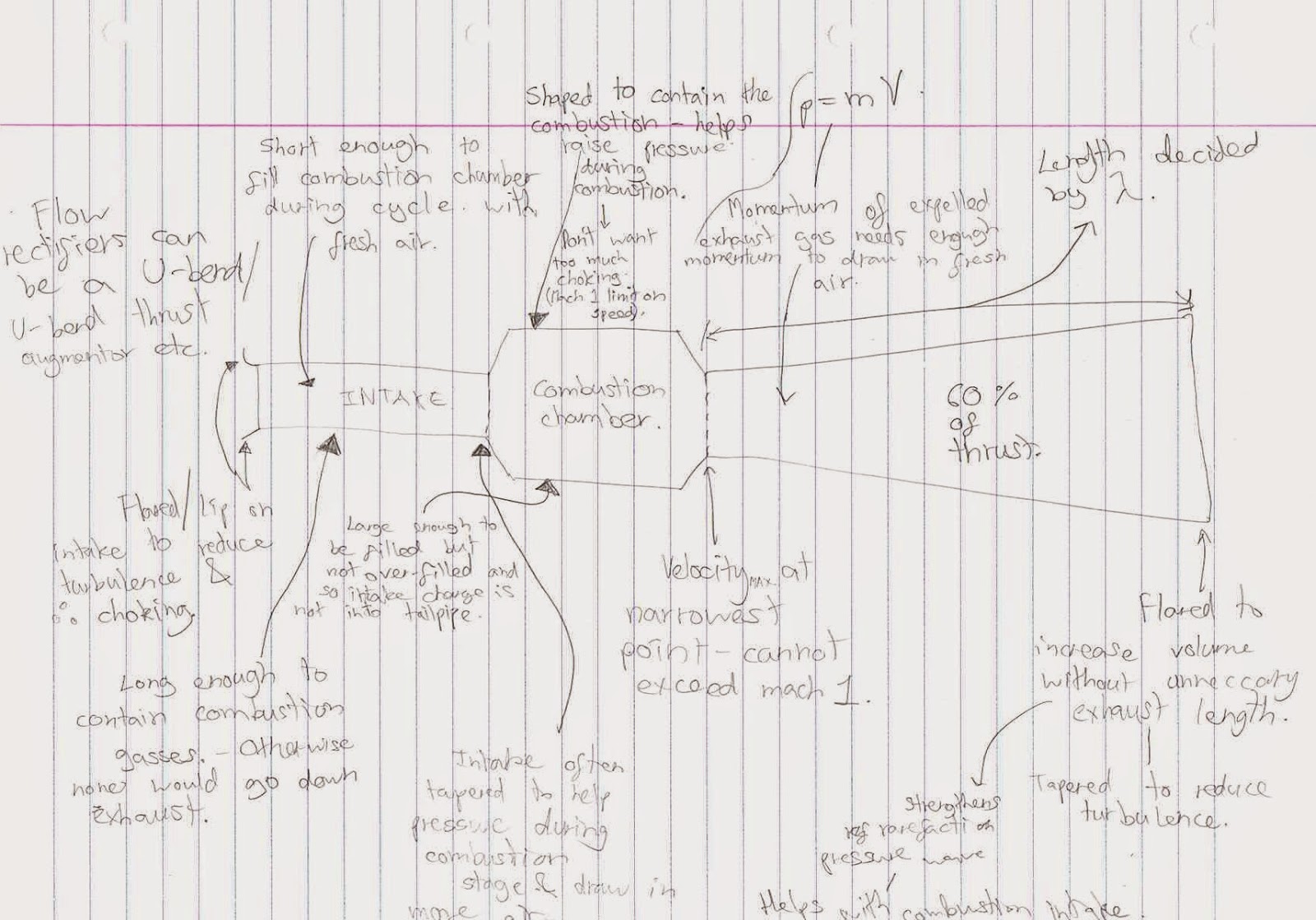
Although I have decided not to pursue the true designing of my pulsejet, I have studied the relevant fluid dynamics and thermodynamics to further my own personal understanding and knowledge of how they function. This will also allow me to possibly verify the design I'm using against some of the simple mathematics and rules of thumb that have been developed.

The further reading I have undertook include 'Heat Engines' F.Metcalfe and various online information about the ideal gas law, Avagrado's hypothesis etc.

This will also hopefully be useful for the EPQ presentation to help me provide me a better basic scientific grounding of their functioning to explain.

Here's some compiled notes from The Enthusiasts Guide (1) showing how some of the dimensions are related and why they need to be:


Sunday 18 January 2015

WELDING PRACTICE 2

I've looked at some youtube welding tutorials and found how important the welder settings are so i'm going to have an experiment with different wire feeds.


After another welding practise, welding seems to already be adequate so I don't think there will be any issues there.


There and no beads that need grinding down like last time  to eliminate the thermal expansion problem and the inside of the weld has much better penetration so it stronger and smoother (roughness would create turbulence and reduce performance). They are good enough for the purpose of this.

Note to self:
Metal gets hot after welding so WEAR GLOVES-thumb is v. sore rn